Table of Materials
|
Serial No. |
Portion |
Material |
|
1 |
Main body |
Polarized rubber |
| 2 |
Lining |
Nylon cord fabric |
| 3 |
Frame |
Hard steel wire |
| 4 |
Union |
Forgeable cast iron |
Techmical Consition
| Parameter |
3/4" --- 3" |
| Working pressure (MPa) |
1.0 |
| Bursting Pressure (MPa |
3.0 |
| Vacuity (mmHg) |
400 |
Table of Nominal Core Diameter of Pige,Axial displacement,and Lateral Displacement
| Nominal core dia.DN |
L Value
(mm) |
Axial displacement (mm) |
Lateral displacement |
| (mm) |
(in.) |
Stretch(mm) |
Compression |
| 15 |
1/2 |
200 |
6 |
22 |
45 |
| 20 |
3/4 |
200 |
6 |
22 |
45 |
| 25 |
1 |
200 |
6 |
22 |
45 |
| 32 |
1 1/4 |
200 |
6 |
22 |
45 |
| 40 |
1 1/2 |
200 |
6 |
22 |
45 |
| 50 |
2 |
200 |
6 |
22 |
38 |
| 65 |
2 1/2 |
200 |
240 |
6 |
22 |
38 |
| 80 |
3 |
200 |
240 |
6 |
22 |
38 |
Schematic Diagram of Displacement and Deflection of Floating Flange Rubber Expansion Joints
|
|
|
|
Axial compression |
Axial stretch |
|
|
|
|
Angle of deflection |
Lateral displacement |
Overview
The rubber joints have been supplied to every aspect of industry and building. They are designed to compensate for axial, lateral, angular movements and vibrations in piping systems and equipment, which operate at varying conditions of pressure and temperature.
Characteristics and Usage
- It employs multi-sphere structure so that the vibration absorption is good and noise reduction efficiency is significant.
- It can bear relatively high working pressure. It features anti-burst and good elasticity.
- It is able to stretch and compress to avoid break of pipes due to thermal expansion and cold deformation.
- It makes easy to remove and replace valves for inspection and repair.
Installation
- Make sure that the sealing faces of the joint bear against mating flanges that are flat and clean over the whole width of the joint.
- Do not use raised face flanges.
- Insert flange bolts with the bolt heads facing the rubber body and nuts on the pipe side.
- Tighten the bolts crosswise, taking up the tension gradually until all the nuts are evenly, tightened.
- Do not over tighten which could damage the sealing face.
- Check that the tightness allows no leakages after the joint has been brought up to pressure.
- Do not paint over the rubber body.
Maintenance and Storage
- Rubber relaxes over a period of time, so it is correct practice to re-check periodically the tightness after a few days.
- Under the average service conditions, the rubber joints will last for many years. However, joints should be inspected for hardening, cracking and swelling periodically, but never longer than one year.
- Rubber joints purchased as spares should be stored in a fairly cool, dry place, protected from direct sunlight. They should be stored flat on the flange face with no weight on top of them.
Pre-installation
- Check that the rubber joint you are installing is compatible with the medium it might handle.
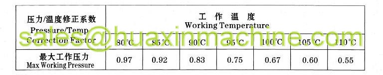
- Check that the rubber joint's rated temperature, pressure and allowable movement will not be exceeded. If the operating temperature is above 70°C, apply the recommended pressure derating.
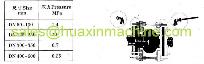
Pressure - Temperature Parameter table:
Location and Control Rods
Ensure that the system is supported so that the joint does not carry the weight of the piping. Rubber joints should be located as close to anchors as possible. If unanchored, check if control rods are required.
If the joints is working against a significant static head, then there should be non-return valve fitted close to the joint.
When a rubber joint is installed in a piping system that is anchored on both sides of the joint, control rods are not required. If one side is unanchored, the joint must be prevented from extending, either by control rods or some other method, if the pressure is higher than:
Different Rubber Materials
The rubber expansion joints are available in a variety of elastomers to give the best possible performance for any set of operation conditions. The popular combinations of lining and cover elastomers are shown below. All of the cover options offer outstanding to very good resistance to sunlight and oxidation. One of these linings will stand up to most chemicals or hydrocarbons or to abrasion.
| Letter Code |
Lining |
Cover |
Color Code |
| EE |
EPDM |
EPDM |
Red |
| NN |
Neoprene |
Neoprene |
Blue |
| RE |
Natural |
EPDM |
White |
| NiN |
Nitrile |
Neoprene |
Yellow |
| HH |
Hypalon |
Hypalon |
Green |
| Rubber Type |
Natural |
EPDM |
Neoprene |
| Max Temp |
80°C |
110°C |
100°C |
| Rubber Type |
Nitrile |
Hypalon |
Butyl |
| Max Temp |
105°C |
105°C |
100°C |
- Natural Rubber: Suitable for water, air, most moderate chemicals, dilute acids and alkalis. Good for abrasion. Not suitable for exposure to strong sunlight, ozone, oil or petroleum.
- EPDM: First choice for hot water, steam, oxidising chemicals, animal and vegetable oils. Excellent for sunlight and ozone. Good for high and low temperature applications.
- Neoprene: Suitable for water, sewage, oxidising chemicals and non-aromatic hydrocarbons. Good for oil resistance and weathering.
- Nitrile: Suitable for most hydrocarbons, oils and petroleum fuels and hydraulic fluids. NOT good for sunlight aging, ozone or flame.
- Hypalon: Suitable for many acids, alkalis, industrial chemicals and aliphatic hydrocarbons. Very good resistance to ozone, sunlight, weathering and abrasion.
- Butyl: Suitable for animal and vegetable oils, water and many oxidising chemicals. Particularly good for low gas permeability. NOT for petroleum fuels or oils.
|